Latitude Stuff - documents


Nothing official - just nice to have
Click on some of the images to ENLARGE

Emer-retrun Landing distance calculator

CPDLC

Initial checklist

All types of approaches

Special procedures


Stockholm Radio HF
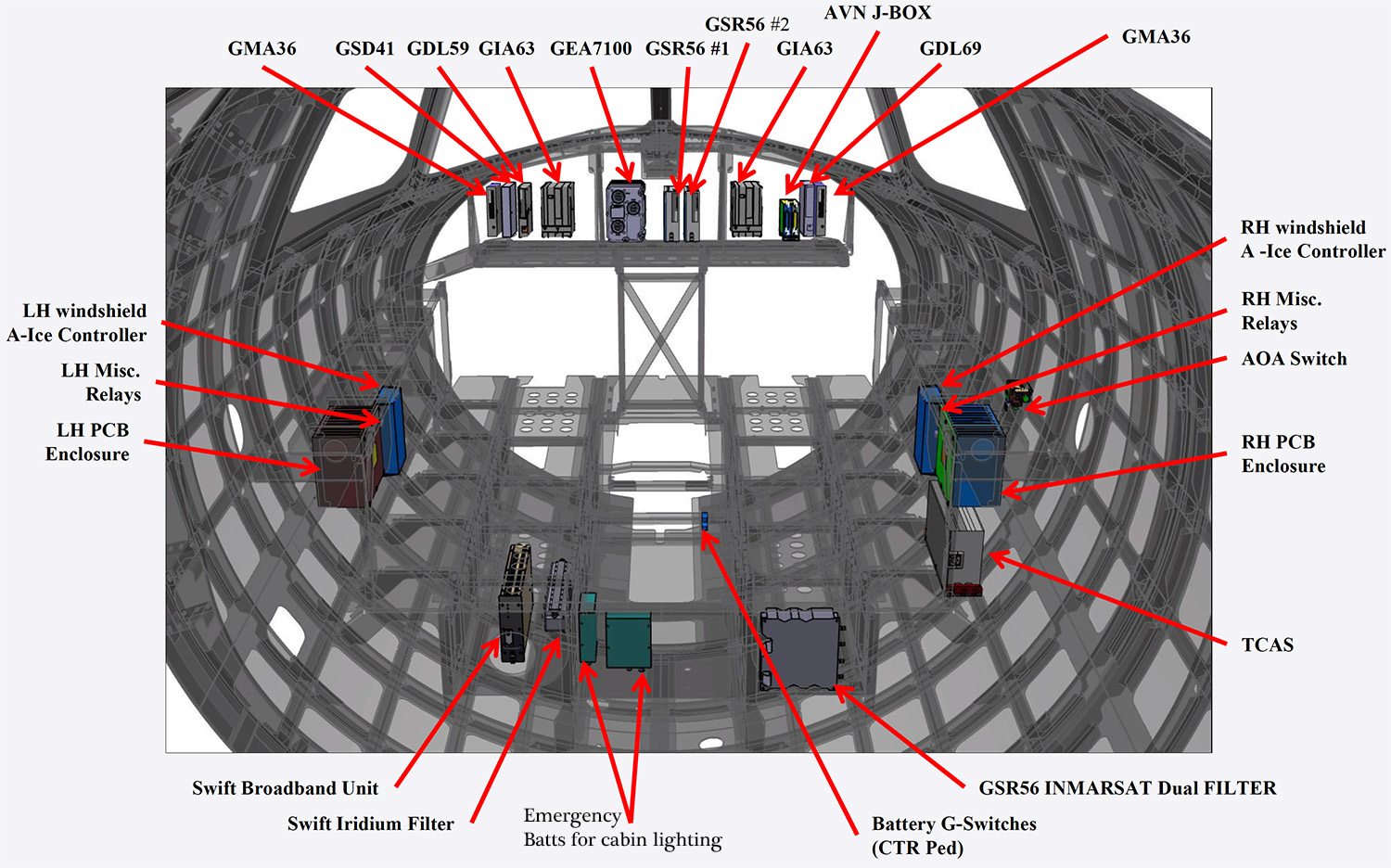
Cockpit equipment
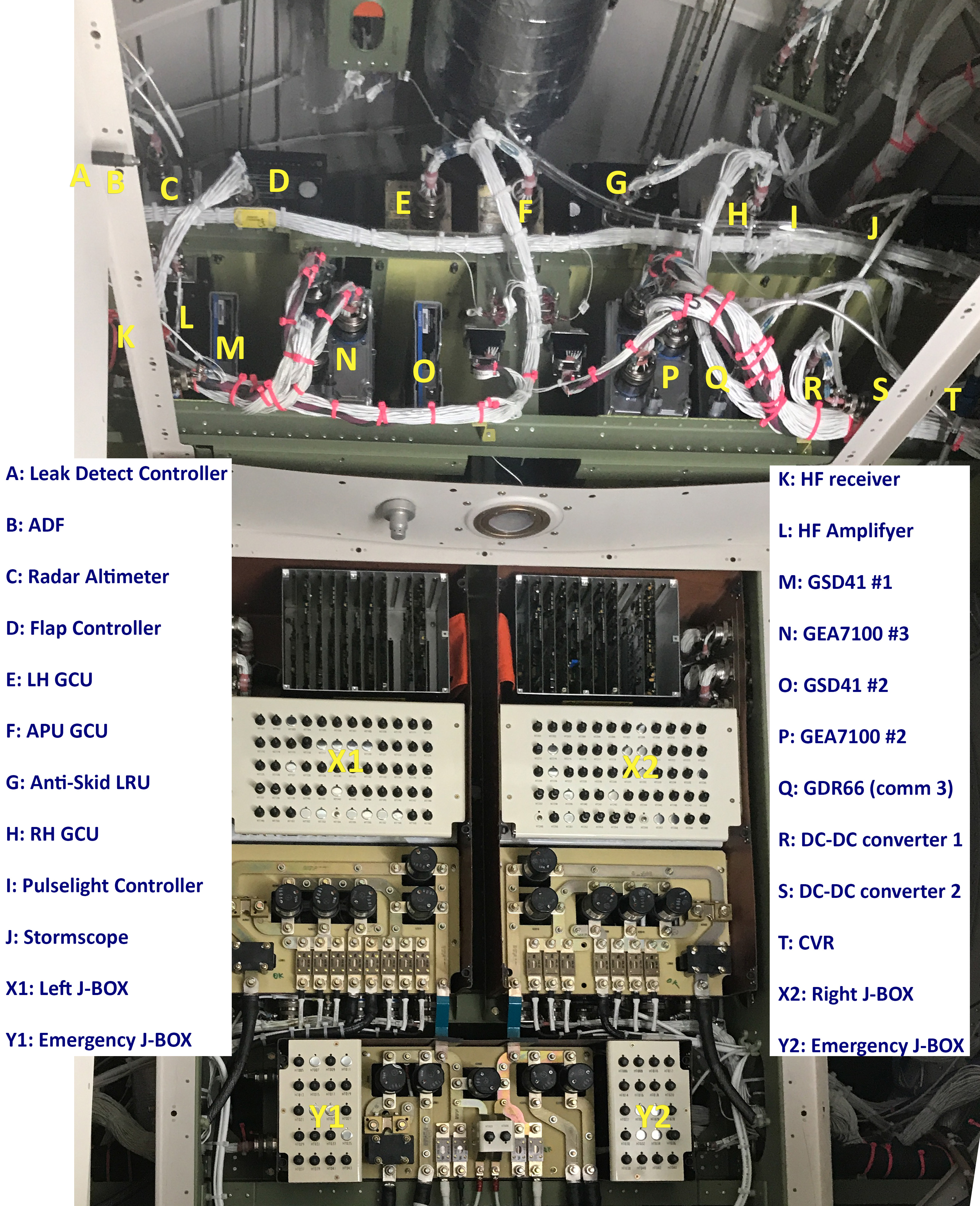
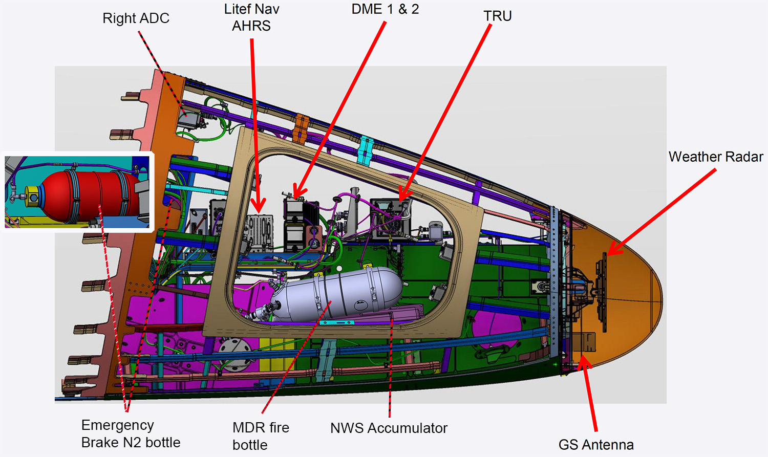
Rear J-BOX and equipment (just aft of the pressure bulkhead)


ACM and toilet j-box

The emergency BATTs & G-switches
The emergency lighting G-switches are co-located with each of the 4 emergency lighting battery packs. If one of the lights remain on after disconnecting the main BATTs one of these g-switches is triggered. The battery pack at the seat locations are located directly outboard of the seat, attached to the lower side wall systems panel. There should be a removable panel on the seat shroud to gain access to them. In the image below (ACM and toilet j-box) there is Batt pack 4 is located under letter M and the image above (cockpit equipment) batt pack 1.

Battery Pack 3

ACM

Anti-ice

De-Ice fluid types


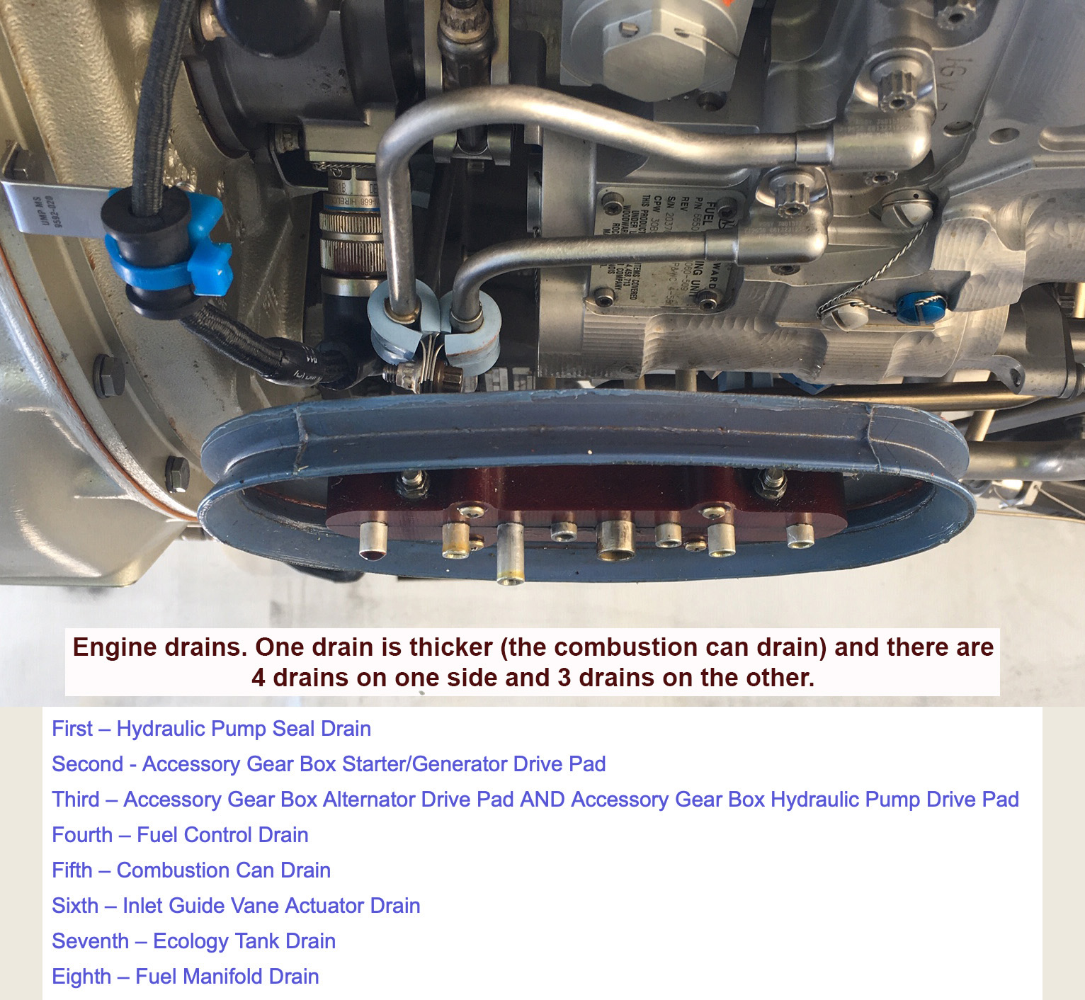
Left Engine

Left engine top view
The control system of the high-pressure bleed air source is the result of throttle lever angle (TLA), aircraft altitude and anti-ice operation. The HP Valve OPEN message will display if the valve is powered closed but the px diff switch sense >5psid from the HP valve which means the HP valve is not completely closed. This message posts in the air after a 5min delay

Right engine
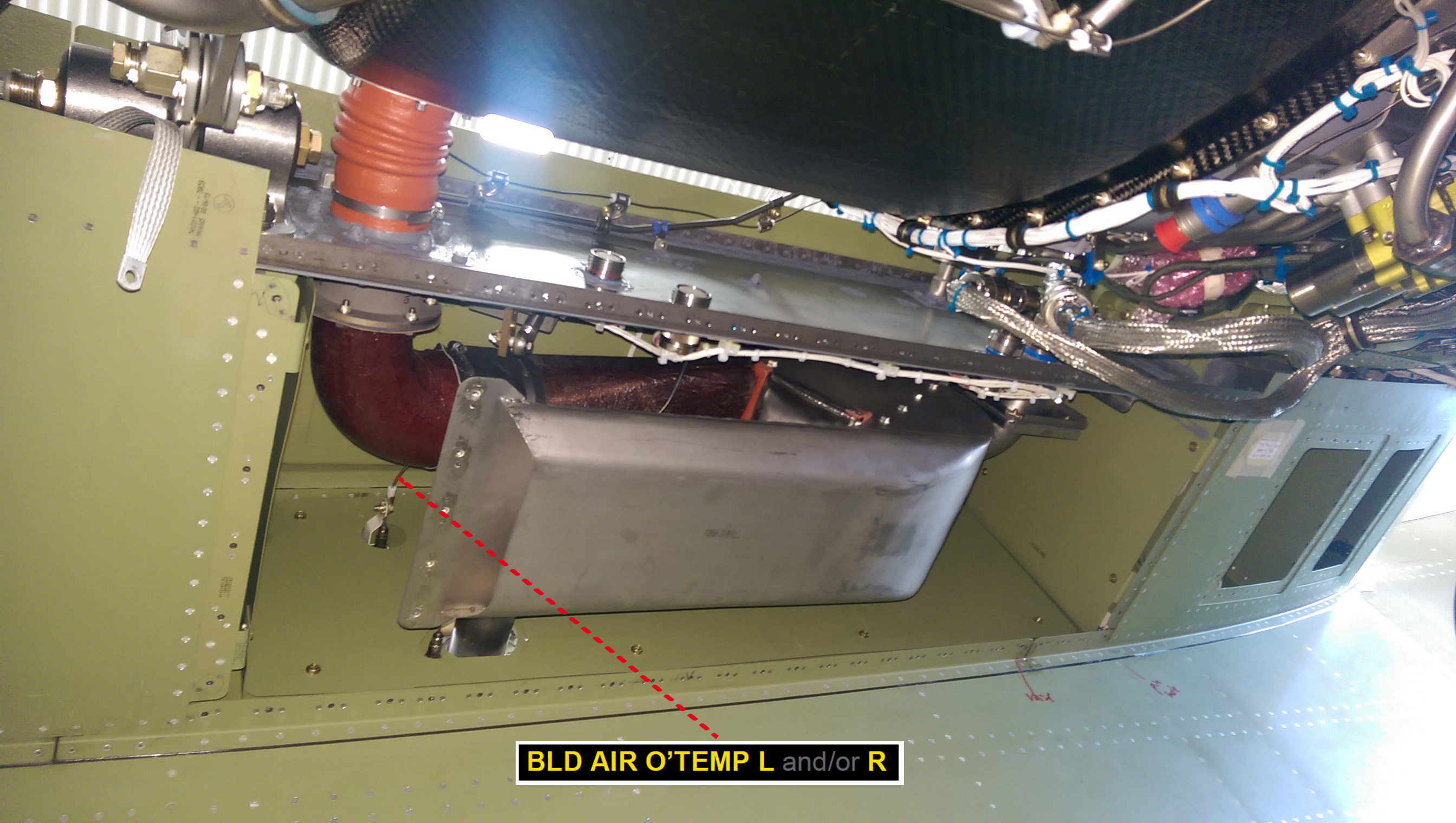
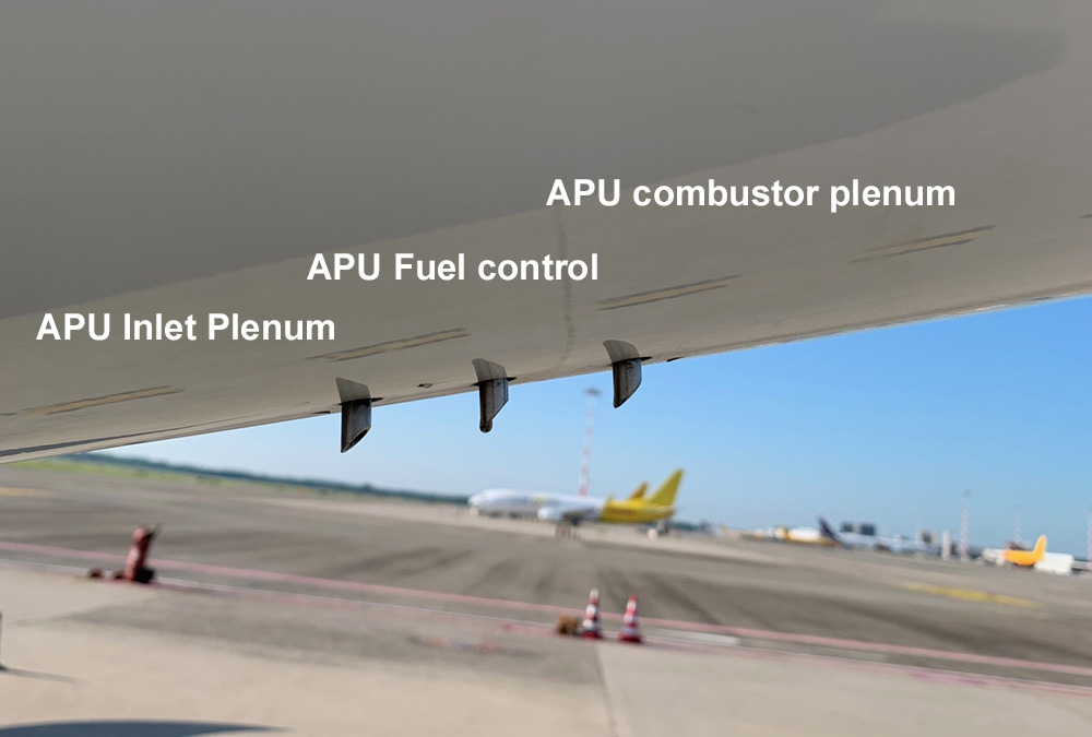
Precooler (Between left engine and airframe)
First exhaust on your right is hot precooler exhaust, the second is cool air from precooler to keep the pilon clean
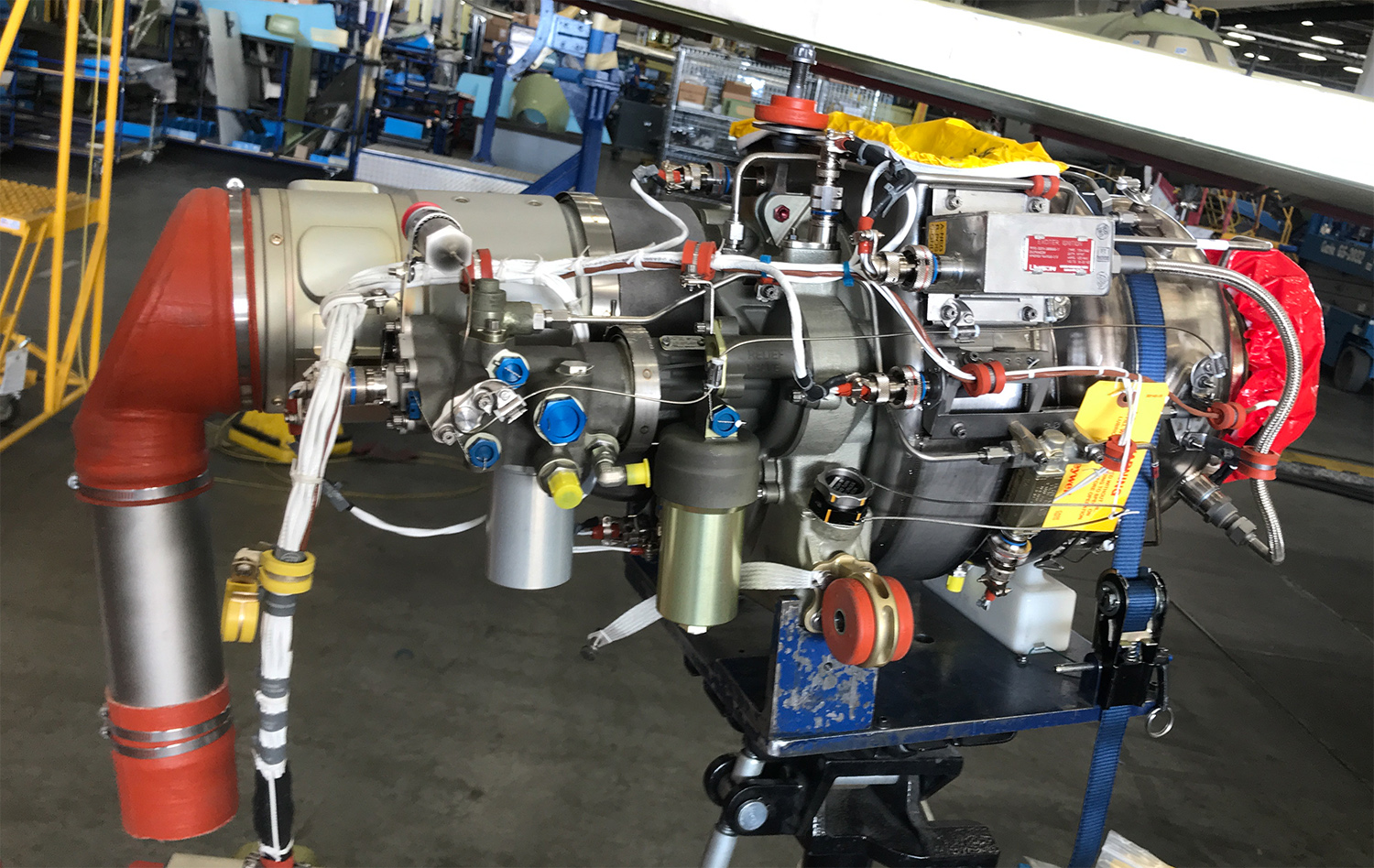
Honeywell RE100 APU
(Exhaust to the right, bleed to the left, intake on the top)
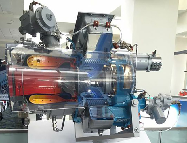
APU cross section, exhaust to the left (this is the Honeywell 36-150, very similar to the RE100 and RE220)
Bleed air is extracted from the compressor section.

Tailcone aft

APU fire extinguisher line has a hole in the Tailcone so the tailcone also gets some Halon.

Hydraulics


Left nose

Emergency Gear extension and Emergency braking
Right nose

Radiation at FL450 in Europe is around 3.5 microSievert per hour, see above. With our flying that is 1500 microSievert in a year above the 3000 microSievert that everybody is exposed to every year. 1500 is comparable to 1 spinal X-ray dose spread out over a year, so not so bad.
100,000 µSv per year is the lowest dose likely linked to increased cancer risk.
Leucotomos Polipodium is a herb that protects against radiation in case you want to protect yourself.
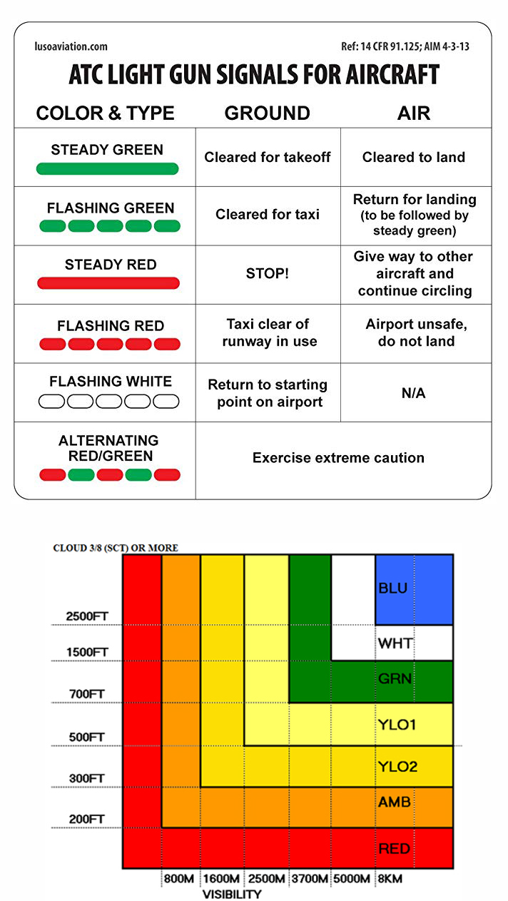
See radiation chart

Gear down ferry. Fuel flow 1800 lbs/hr @ 180 IAS (240 TAS)
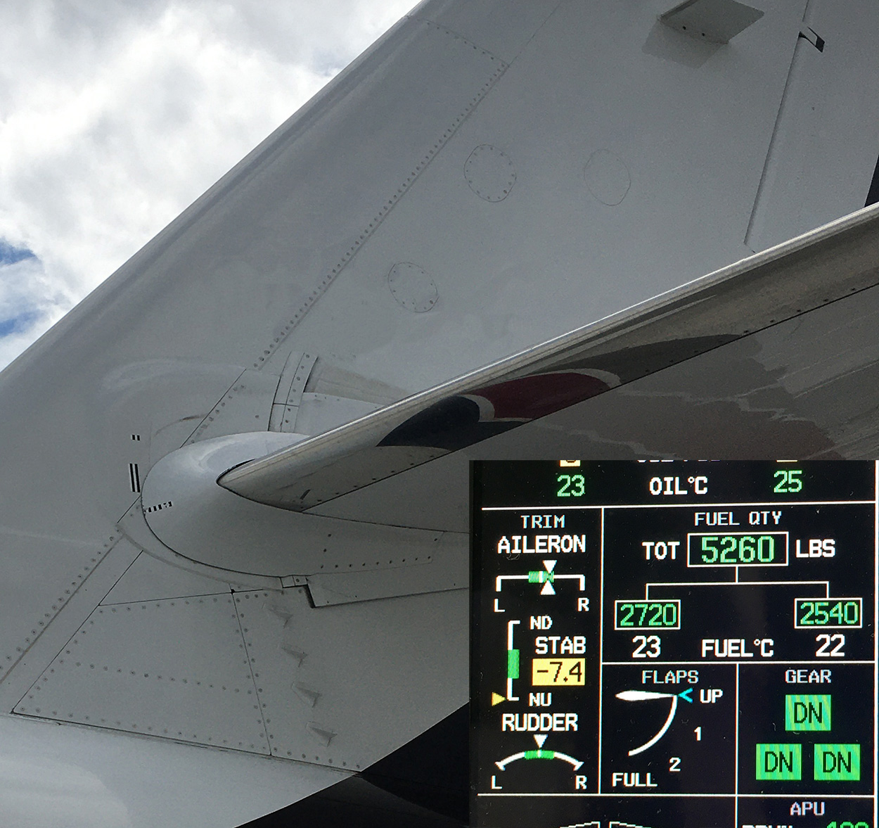
-7.4 max nose up Trim (Also check the trim tab being 1 inch down in this state)

Mach trim check -7.4

1.2 Max nose down Trim

The FAILED PATH message in the Garmin system means that there is a component or part of the avionics that is not communicating. In this case, it is the HF1 message causing it.
The HF 1 FAIL message indicates that the coupler has failed due to low internal nitrogen pressure. The coupler itself is a sealed unit that couples (tunes) the HF antenna and then sends the high wattage RF transmission. We use nitrogen to purge air from inside the coupler case to eliminate arcing at altitude. The case is pressurized to eliminate moisture intrusion. This message is alerting the crew that a pressure sensor inside the coupler senses a low pressure. As a result, the HF is disabled. This is not a grounding item, just an advisory.
The GPS Service message indicates that the Garmin System has detected a problem with the #2 GPS. The #2 GPS lives inside GIA #2. The GIA is still operating, but the #2 GPS has failed by itself. The only corrective action here would be to replace the #2 GIA, but a BATT disconnect for 30 minutes will often do the trick as well.

No difference, but officially PB - on for check.


Numbers 1

Numbers 2
Numbers 3


Driftdown airports

Drifdown altitude with anti-ice off - nice to know if you will enter the top of the clouds and enter icing conditions. If so, your driftdown is going to be 10-15% lower, so think of the MORA and options.